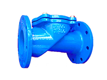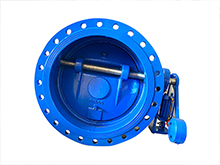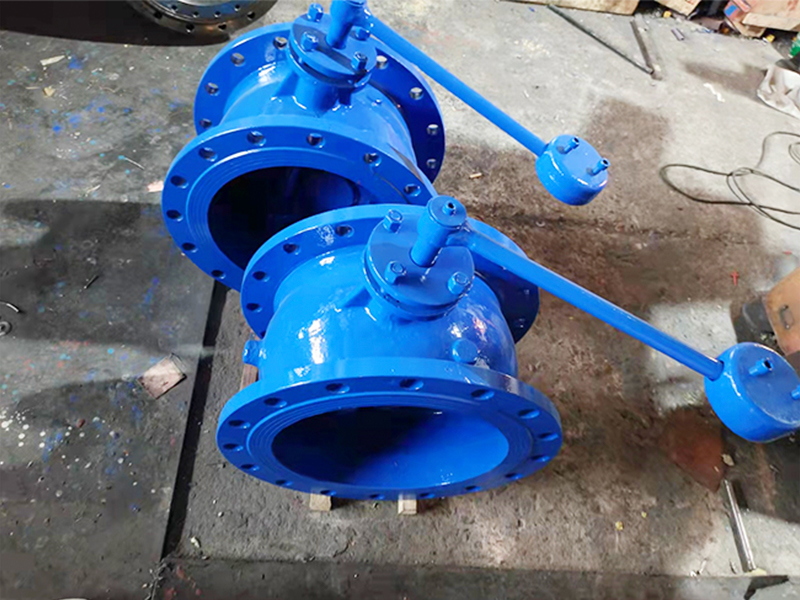
check valve with counter weight
Features:
Size: 8"~80"(DN200 to DN2000)
Pressure rating: PN10, PN16
Material: Body: GGG40, GGG50 Disc: GGG40, GGG50, SS304, SS316 Stem : 1Cr13, SS304, SS316 Seal : NBR, EPDM
Operated type: Hydraulic
Structure: Tilting disc, with lever and counter, hammer
Medium: Water, sewage
Temperature: 10 to 80°C
We're here to help:
Easy ways to get the answers you need.
Parameter:
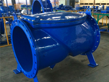
The buffer check valve produced by our factory is mainly used at the pump outlet of industrial water supply and sewage treatment plant to prevent the backflow of the medium in the pipe network. Destructive water hammer is automatically eliminated so that pumps and piping are not damaged. The valve is mainly characterized by valve body, cutting flap and good buffer performance. It is the best product for industrial water and urban sewage.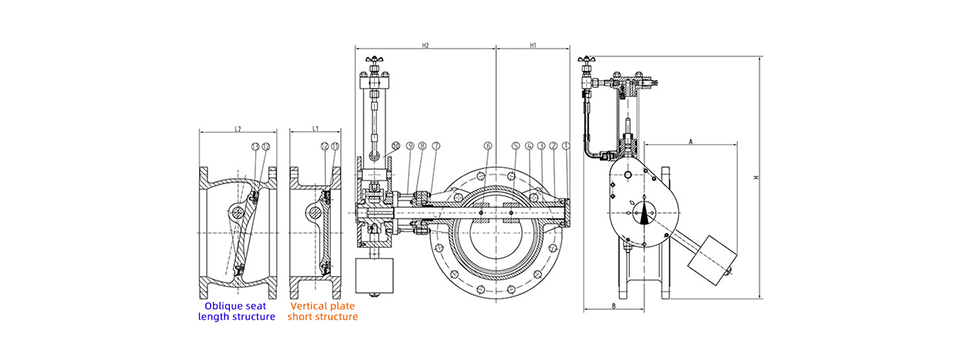
Main external connection dimensions
|
DN(mm) |
200 |
250 |
300 |
350 |
400 |
450 |
500 |
600 |
700 |
800 |
900 |
1000 |
1200 |
1400 |
|
L |
230 |
250 |
270 |
290 |
310 |
330 |
350 |
390 |
430 |
470 |
510 |
550 |
630 |
710 |
|
H |
550 |
630 |
690 |
780 |
860 |
910 |
980 |
1070 |
1220 |
1320 |
1430 |
1550 |
1800 |
1980 |
|
B1 |
540 |
600 |
650 |
710 |
770 |
830 |
900 |
1090 |
1200 |
1320 |
1420 |
1550 |
1780 |
2000 |
WEIZIDOM Advantages
1.WEIZIDOM patent products, patent certification
The product side flanges comply with national, German, Russian, American, British and Japanese standards and other domestic and international standards for multiple pressures, easy connection and wide adaptability, which can reduce the type of purchase and stock.
2.The product has an independent identity to ensure traceability
Each WEIZIDOM product has its own unique identification number, to ensure product traceability.
3.Provide material inspection report
All WEIZIDOM products can provide the material inspection report of the main parts.
4.One-stop service
One-stop service, we not only supply high quality products, also supply solutions and after-sales service.
5.WEIZIDOM has a lot of project experience
We have a lot of project experience in countries such as Pakistan and the Philippines, WEIZIDOM has always been noticed all over the world, and trust comes from quality.
6. WEIZIDOM has a strict quality control system
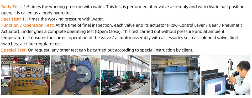
WEIZIDOM has a strict quality control system and before delivery, we test 100% of each product to ensure its quality, promising you a high quality product.
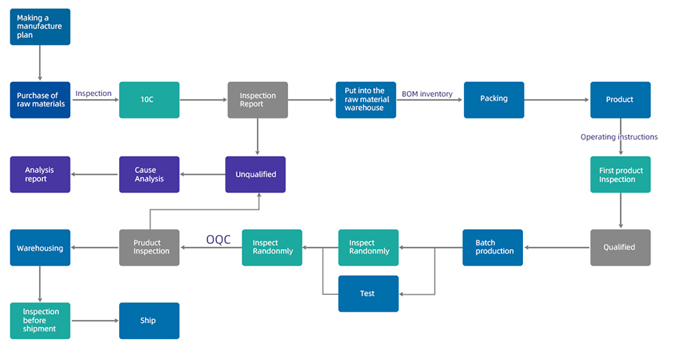
Quality Control Process
Standards&Features:
Check valve is mainly composed of valve body, butterfly plate, regulating valve, and buffer cylinder. Buffer cylinder is also composed of two oil chambers, connected internally by a one-way valve, and externally connected by a regulating valve. When the valve is opened, the medium water pushes the butterfly plate.
At this time, the hydraulic oil in the buffer cylinder quickly flows from cavity 1 to cavity 2 through the check valve inside. When the valve is closed, the medium returns to the first cavity.
Due to the large impact force of the counterweight and the high pressure wave, the valve flap is mostly closed, and the oil in the second cavity is compressed at the same time. Normal opening of the regulating valve is only 1/3. The high pressure oil compressed in the 2 cavity can only flow slowly into the 1 cavity through this 1/3 area, so that the valve flap is slowly closed and the pressure of the water hammer peak is weakened. Limits the generation of destructive water hammer.
Due to the function of the above-mentioned regulating valve, the time for the hydraulic oil to flow from cavity 2 back to cavity 1 can be adjusted by adjusting its opening. That is to adjust the closing speed of the valve. Therefore, when the opening degree of the regulating valve is smaller, closing speed of the corresponding valve is slower. Then longer the water discharge, the smaller the water hammer, and vice versa. Users can adjust appropriately according to the needs of the scene.
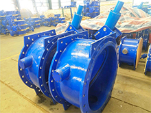
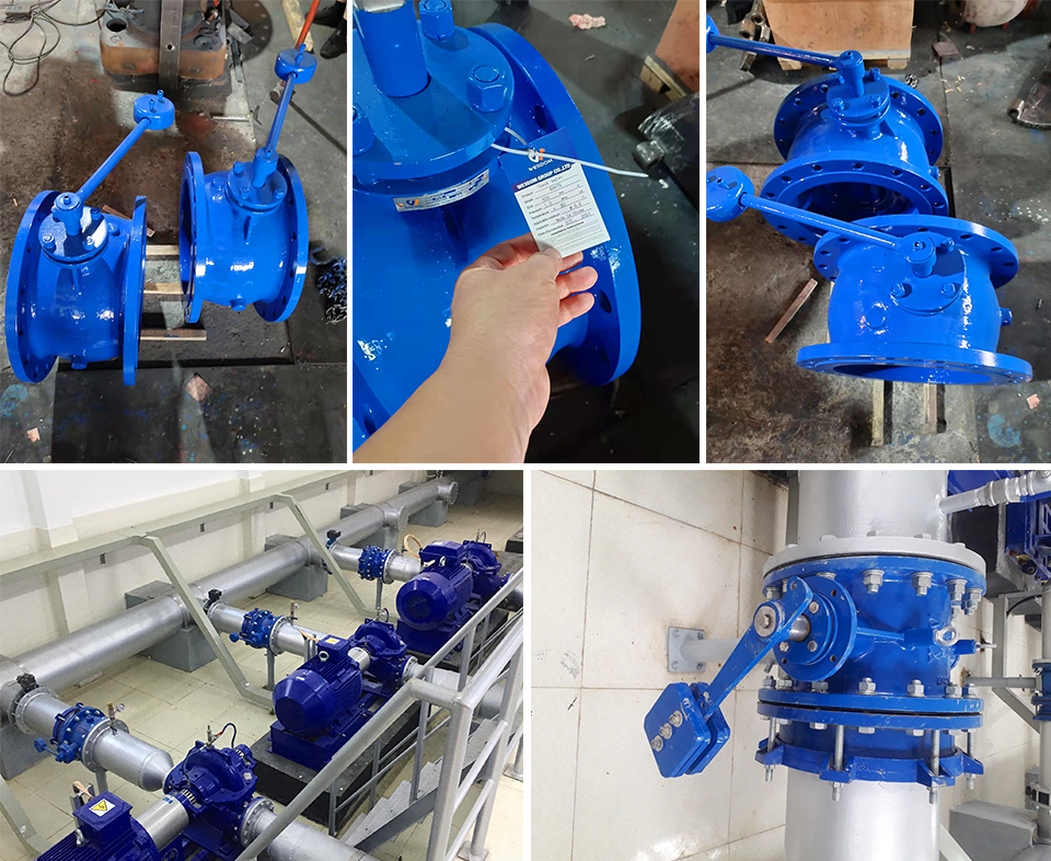
Case:
Project description:
WEIZIDOM customizes the most suitable solutions for customers according to the actual needs of customers’ working conditions;
Client feedback:
WEIZIDOM products are of high quality, Now all products have well installed on site.
Project pictures:
Application:
Flow Regulation and Isolation:
Butterfly valves are commonly used for regulating and isolating flow in various industries. If the hypothetical "butterfly buffering check valve" combines the flow control capabilities of a butterfly valve, it could be used in applications where precise flow regulation is required, such as in water treatment plants, HVAC systems, and chemical processing plants.
Pressure Relief and Protection:
If the valve incorporates the features of a buffering valve or pressure relief valve, it could serve as a safety device to protect the system from overpressure. In this case, it could be used in applications such as steam systems, hydraulic systems, or compressed air systems, where pressure control and protection are critical.
Backflow Prevention:
If the valve incorporates the characteristics of a check valve, it could be used to prevent backflow in pipelines or systems. This would be particularly useful in applications where the reversal of flow could cause damage or contamination, such as in pumping systems, water supply networks, wastewater treatment plants, and irrigation systems.
Please fill in your procurement needs and contact information