
- Gate valve
-
- DN1000 Extension stem double flange soft seal gate valveDIN F4 resilient seated gate valveDN450-1200 Resilient Seated Gate ValveDIN F5 resilient seated gate valveSocket connection soft seal gate valveUnderground cap soft seal gate valveBS5163 rising stem soft seal gate valveHard seal gate valveAPI slab Gate ValveStainless steel flange gate valveWafer knife gate valvePneumatic gate valveSoft seal gate valveExtension stem gate valveUL/FM fire protection groove ends gate valveRising stem forged steel gate valvecarbon steel gate valveStainless steel threaded gate valveDIN soft seal gate valveANSI soft sealing gate valve 200PSICast iron gate valveBS resilient seated gate valve
- Butterfly valve
-
- DN900 pneumatic triple eccentric hard seal butterfly valveD643H Triple Eccentric Butterfly ValveD343H Hard seal butterfly valveMulti standard EPDM seated butterfly valveSingle flange butterfly valveDN2000 Double eccentric butterfly valveFlange butterfly valveLug butterfly valveWafer butterfly valve with handleWorm gear operated butterfly valveWafer lined fluorine butterfly valveStainless steel wafer butterfly valveStainless steel flanged butterfly valveThree eccentric flange butterfly valvePneumatic flanged butterfly valvePneumatic wafer butterfly valveTriple eccentric butterfly valve wafer typeWafer butterfly valve ULC approvedInflatable seat butterfly valveHigh performance butterfly valveGrooved end butterfly valveElectric soft seal butterfly valveFlange fluorine lined butterfly valveHandle aluminum butterfly valveWorm Gear Aluminum Butterfly ValveFull PTFE lined butterfly valve wafer typeOne stem no-pin wafer butterfly valveMulti standard aluminum stem butterfly valveStainless Steel wafer Butterfly ValveAluminium handle operated lug butterfly valveLever Operated Flange Butterfly ValveButterfly valve stemButterfly valve discButterfly valve seat
- Ball valve
-
- DN1400 top-mounted eccentric semi-ball valveFlanged three-way ball valveFully welded ball valveNatural gas ball valveHigh platform flange ball valve1 PC ball valveFixed ball valvePTFE seat flanged ball valveMetal seat ball valveAPI 6D ball valve3 Piece ball valveFull Bore 3 way ball valve L-Port3 Way T-Port ball valve2PC Ball valve female thread stainless steel
- Globe Valve
-
- API Carbon Steel Globe ValveBellows Globe ValveStainless steel flange globe valveStainless steel thread S type globe valveStainless steel thread B type globe valveCast Steel Globe ValvePiston Globe ValveWCB Carbon Steel Globe Check Valveelectric motorized control stainless steel SS316 globe valveBrass Globe ValveCryogenic Globe valveHT200 Globe ValveThreaded Stainless Steel Globe ValveGG25 Globe ValveANSI API Cast Steel And Stainless Steel Globe valve
- Check valve
-
- Rubber seal check valveDN800 Slow closing check valveDN800 Rubber Disc Check ValveButterfly Buffering Check Valvecheck valve with counter weightSilent Check ValveWCB Swing check valveSwing Check ValveSingle Chip Check Valve H74WStainless Steel Wafer Check ValveSwing Start Check ValveFoot check valveAPI Swing Check ValveDIN Flange check valveSingle plate check valveLifting Check ValveBottom ValveHammer Diminish Noises Check ValveWafer Check ValveWafer dual plate check valve
- Control valve
-
- Static Balancing ValveCage Guided Sleeve Globe Control ValveDN1000 Piston Flow Regulating ValveDN1600 Electric Actuator Flow Regulating ValvePneumatic Flanged Butterfly ValvePneumatic Wafer Butterfly ValveAngle Seat ValvePneumatic gate valveElectric three-way control valveElectric sleeve control valve
- Water Meter
-
- Vertical Type Water MetersStainless steel threaded water meterPiston water meterPlastic water meterMore flow rotor dry water meterspiral vane flange water meterCI wotlman water meter with pulse outputLXCLG(R) Vertical removable element woltman cold (hot) water meterSingle flow rotor dry water meterPrepaid Token Water MeterElectromagnetic flowmeterRotary Piston Liquid Sealed Water MeterRotary Piston Liquid Sealed Water Meter
- Air valve
-
- Double ball exhaust valveDoubleair Air Valve SaudiDoubleair Air Valve Southeast AsiaDoubleair Air Valve South AmericaDouble Air ValveThreaded Air ValveSingle Air ValveTriple Functions Air ValveAutomatic Air Release ValveAutomatic release valveAutomatic exhaust valveComposite Exhaust Air ValveBrass exhaust valveDouble Ball Air Valve
- Pipe Repair & Coupling
-
- Flexible Multi-Function Pipe Coupling ZFJ-SSS Semi-Circle Pipe Repair Clamp SJW-HDuctile Iron Band Repair ClampStainless Steel Band Repair ClampDouble-Section Pipe Repair CouplingFolding Type Pipe RepairSingle-Section Multi-Function Pipe Coupling MF-SGear-Ring Type Multi-Function Pipe Coupling GR-SZBW Damping Corrugated Hose
- Dismantling Joint
-
- VSSJAFC(CC2F) Detachable Flange Transmission JointVSSJA-2(B2F) Double Flange Limited Expansion JointVSSJA-1(BF) Single Flange Limited Expansion JointVSSJA(AF) Flange Loose Expansion JointJGD-B Threaded Rubber JointZBW Damping Corrugated HoseKXT-S Flexible Dual-Spherical Rubber JointKXT Rubber Soft JointFlange Adaptor
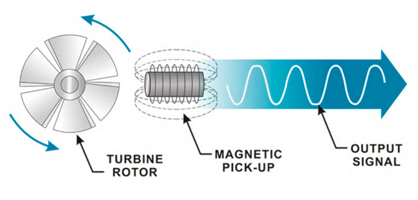
How Turbine Flow Meters Work?
It is mainly composed of turbine, deflector, casing and magnetoelectric sensor, etc. The bearing of the rotating shaft of the turbine is supported by the deflector fixed on the casing. The casing is made of non-magnetic stainless steel, and the turbine is magnetically conductive stainless steel, which usually has 4 to 8 helical blades.
As fluid passes through the flow meter, the turbine is driven to rotate at a speed that is a function of fluid flow. The frequency of the output pulse signal of the non-contact magnetoelectric rotational speed sensor installed outside the casing is proportional to the rotational speed of the turbine. Therefore, the flow rate of the fluid can be determined by measuring the output frequency of the sensor.
In order to reduce the axial thrust of the fluid acting on the turbine, the reverse thrust method is used to automatically compensate the axial thrust. It can be seen from the geometry of the turbine that when the fluid flows through the k-k section, the flow velocity increases and the static pressure decreases. An unequal static pressure field is generated between them. The pressure difference formed by it causes the force acting on the turbine rotor (the axial component of this force is opposite to the axial thrust of the fluid) to offset the axial thrust of a part of the fluid, thereby reducing the axial load of the bearing. The use of automatic axial thrust compensation can improve the life and accuracy of the instrument.
There is a deflector composed of a guide ring and a guide seat at the fluid inlet, which guides the fluid straight before it reaches the turbine and avoids changing the action angle between the fluid and the turbine blades due to the spin of the fluid, thereby ensuring the accuracy of the instrument. In order to further reduce the influence of fluid spin, a straight pipe section with the same diameter as its diameter should be installed before and after the flowmeter. Generally, thelength of the straight pipe section at the fluid inlet is more than 10 times the diameter of the pipe, and the length of the straight pipe section at the outlet is not less than 5 times the diameter.
If the friction of the bearing and the power loss of the turbine are ignored, the relationship between the fluid flow qv through the flowmeter and the frequency of the pulse signal output by the sensor is:
The characteristics of the turbine flow sensor are: high precision, wide measurement range, good repeatability, high pressure resistance, corrosion resistance, digital signal output, simple structure, and convenient use and maintenance. Its limitations are: regular calibration is required, the ordinary type is not suitable for medium with higher viscosity, the fluid density and viscosity have a great influence on the flow characteristics, and the cleanliness of the measured medium is required to be high, and the performance of small-diameter instruments is seriously affected by the flow characteristics.