

- Gate valve
-
- BS5163 rising stem soft seal gate valveDN1000 Extension stem double flange soft seal gate valveWEIZIDOMDIN F4 resilient seated gate valveDN450-1200 Resilient Seated Gate ValveDIN F5 resilient seated gate valveSocket connection soft seal gate valveWEIZIDOMUnderground cap soft seal gate valveHard seal gate valveAPI slab Gate ValveStainless steel flange gate valveWafer knife gate valvePneumatic gate valveSoft seal gate valveExtension stem gate valveUL/FM fire protection groove ends gate valveRising stem forged steel gate valvecarbon steel gate valveStainless steel threaded gate valveDIN soft seal gate valveANSI soft sealing gate valve 200PSICast iron gate valveBS resilient seated gate valve
- Butterfly valve
-
- DN900 pneumatic triple eccentric hard seal butterfly valveD643H Triple Eccentric Butterfly ValveD343H Hard seal butterfly valveMulti standard EPDM seated butterfly valveSingle flange butterfly valveDN2000 Double eccentric butterfly valveFlange butterfly valveLug butterfly valveWafer butterfly valve with handleWorm gear operated butterfly valveWafer lined fluorine butterfly valveStainless steel wafer butterfly valveStainless steel flanged butterfly valveThree eccentric flange butterfly valvePneumatic flanged butterfly valvePneumatic wafer butterfly valveTriple eccentric butterfly valve wafer typeWafer butterfly valve ULC approvedInflatable seat butterfly valveHigh performance butterfly valveGrooved end butterfly valveElectric soft seal butterfly valveFlange fluorine lined butterfly valveHandle aluminum butterfly valveWorm Gear Aluminum Butterfly ValveFull PTFE lined butterfly valve wafer typeOne stem no-pin wafer butterfly valveMulti standard aluminum stem butterfly valveStainless Steel wafer Butterfly ValveAluminium handle operated lug butterfly valveLever Operated Flange Butterfly ValveButterfly valve stemButterfly valve discButterfly valve seat
- Ball valve
-
- DN1400 top-mounted eccentric semi-ball valveFlanged three-way ball valveFully welded ball valveNatural gas ball valveHigh platform flange ball valve1 PC ball valveFixed ball valvePTFE seat flanged ball valveMetal seat ball valveAPI 6D ball valve3 Piece ball valveFull Bore 3 way ball valve L-Port3 Way T-Port ball valve2PC Ball valve female thread stainless steel
- Globe Valve
-
- API Carbon Steel Globe ValveBellows Globe ValveStainless steel flange globe valveStainless steel thread S type globe valveStainless steel thread B type globe valveCast Steel Globe ValvePiston Globe ValveWCB Carbon Steel Globe Check Valveelectric motorized control stainless steel SS316 globe valveBrass Globe ValveCryogenic Globe valveHT200 Globe ValveThreaded Stainless Steel Globe ValveGG25 Globe ValveANSI API Cast Steel And Stainless Steel Globe valve
- Check valve
-
- Rubber seal check valveDN800 Slow closing check valveDN800 Rubber Disc Check ValveButterfly Buffering Check Valvecheck valve with counter weightSilent Check ValveWCB Swing check valveSwing Check ValveSingle Chip Check Valve H74WStainless Steel Wafer Check ValveSwing Start Check ValveFoot check valveAPI Swing Check ValveDIN Flange check valveSingle plate check valveLifting Check ValveBottom ValveHammer Diminish Noises Check ValveWafer Check ValveWafer dual plate check valve
- Control valve
-
- Static Balancing ValveCage Guided Sleeve Globe Control ValveDN1000 Piston Flow Regulating ValveDN1600 Electric Actuator Flow Regulating ValvePneumatic Flanged Butterfly ValvePneumatic Wafer Butterfly ValveAngle Seat ValvePneumatic gate valveElectric three-way control valveElectric sleeve control valve
- Water Meter
-
- Vertical Type Water MetersStainless steel threaded water meterPiston water meterPlastic water meterMore flow rotor dry water meterspiral vane flange water meterCI wotlman water meter with pulse outputLXCLG(R) Vertical removable element woltman cold (hot) water meterSingle flow rotor dry water meterPrepaid Token Water MeterElectromagnetic flowmeterRotary Piston Liquid Sealed Water MeterRotary Piston Liquid Sealed Water Meter
- Air valve
-
- Double ball exhaust valveDoubleair Air Valve SaudiDoubleair Air Valve Southeast AsiaDoubleair Air Valve South AmericaDouble Air ValveThreaded Air ValveSingle Air ValveTriple Functions Air ValveAutomatic Air Release ValveAutomatic release valveAutomatic exhaust valveComposite Exhaust Air ValveBrass exhaust valveDouble Ball Air Valve
- Pipe Repair & Coupling
-
- Flexible Multi-Function Pipe Coupling ZFJ-SSS Semi-Circle Pipe Repair Clamp SJW-HDuctile Iron Band Repair ClampStainless Steel Band Repair ClampDouble-Section Pipe Repair CouplingFolding Type Pipe RepairSingle-Section Multi-Function Pipe Coupling MF-SGear-Ring Type Multi-Function Pipe Coupling GR-SZBW Damping Corrugated Hose
- Dismantling Joint
-
- VSSJAFC(CC2F) Detachable Flange Transmission JointVSSJA-2(B2F) Double Flange Limited Expansion JointVSSJA-1(BF) Single Flange Limited Expansion JointVSSJA(AF) Flange Loose Expansion JointJGD-B Threaded Rubber JointZBW Damping Corrugated HoseKXT-S Flexible Dual-Spherical Rubber JointKXT Rubber Soft JointFlange Adaptor
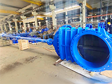
What exactly is the function of the exhaust valve in the HAVC system?
What is an Air Valve?
An Air Valve (also known as an automatic air release valve or automatic air vent) is a small, self-operating device designed to automatically release trapped air from a liquid-filled piping system while preventing liquid from escaping. In HVAC and plumbing systems, air pockets can form at high points in pipelines, causing reduced flow efficiency, noise, corrosion, and water hammer. The air valve solves this problem by venting accumulated air automatically — without any manual intervention or external power.

The operating principle is simple and ingenious:
* The valve contains a float mechanism (usually a hollow ball or cylindrical float) that rises and falls with the liquid level
* When air accumulates in the valve body, the liquid level drops, causing the float to descend
* As the float descends, it opens a small orifice (vent port) , allowing trapped air to escape
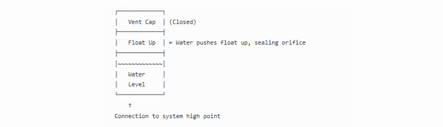
* When liquid re-enters the valve body, the float rises and seals the orifice , preventing liquid from leaking out
* The cycle repeats automatically whenever air accumulates
Key characteristics of Air Valves:
Fully automatic operation – No manual intervention, no external power required
Compact size – DN15 to DN25 (½" to 1") — fits easily at pipeline high points
Continuous air release – Releases small pockets of air as they accumulate during normal system operation
Sealed construction – Prevents leakage when the system is under pressure
Maintenance-free – Simple float mechanism with long service life
Brass construction – Corrosion-resistant for water and mild chemical service
At WEIZIDOM, our Air Valves are manufactured to ISO228 design standards with strict quality control (12 tests from raw material to final product), ensuring reliable, automatic air release for water, gas, and other liquid-filled systems.
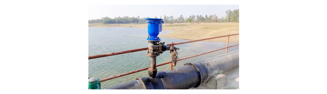
Main Function in HVAC Systems
In HVAC systems, the Air Valve serves as an essential air management device that removes trapped air from liquid-filled piping systems, improving efficiency, reducing noise, and preventing damage.
Its primary functions include:
|
Function |
Description |
|
Removing Trapped Air from Chilled Water Lines |
Air pockets in chilled water pipes reduce cooling capacity, create flow noise, and cause uneven cooling. Air valves installed at high points automatically vent this air, ensuring efficient system operation. |
|
Venting Air from Hot Water Heating Lines |
Air in hot water systems causes gurgling noises in radiators, reduces heat output, and can lead to pump cavitation. Air valves release air from radiators, baseboard heaters, and main supply lines. |
|
Preventing Air Locks in Pumped Systems |
Accumulated air can create air locks that block flow entirely — preventing water from reaching terminal units. Air valves break air locks by releasing trapped air at strategic high points. |
|
Reducing Corrosion by Removing Oxygen |
Dissolved oxygen in water accelerates corrosion of pipes and equipment. By venting air from the system, air valves reduce the oxygen content, extending the service life of the HVAC system. |
|
Eliminating Water Hammer from Air-Related Surges |
Compressed air pockets can suddenly release, causing pressure surges (water hammer) that damage pipes and fittings. Air valves prevent this by removing air before it can accumulate. |
|
Facilitating System Start-Up & Filling |
When filling an empty HVAC system, air must be displaced by water. Air valves automatically vent this air during filling, allowing complete and rapid system fill without manual bleeding. |
Typical applications within water and gas systems include:
|
Application Field |
Specific Use |
|
Chilled Water Systems |
High point vents on supply and return mains, air separator vents |
|
Hot Water Heating Systems |
Radiator vents, baseboard heater vents, boiler air vents, main line high point vents |
|
Hydronic Piping |
Air separator vents, expansion tank connections, pump suction line vents |
|
Solar Thermal Systems |
High point vents on collector loops, storage tank connections |
|
Geothermal Heat Pump Loops |
High point vents on ground loops, buffer tank connections |
|
Water Supply Lines |
High point vents in building water distribution, pressure tank vents |
|
Compressed Air Systems |
Drain points for condensate and air release (note: for liquid lines, not dry air lines) |
Key Features & Advantages
WEIZIDOM’s Air Valve is engineered specifically for HVAC and plumbing systems, providing automatic, maintenance-free air release.
Below are its outstanding features and advantages:
|
Feature |
Advantage |
|
ISO228 Compliance |
Manufactured to international thread standard for pipe threads — ensures compatibility with standard BSP or BSPT threaded pipe fittings worldwide. |
|
Compact Diameter Range (DN15–DN25 / ½"–1") |
Small size fits easily at pipeline high points, radiator tops, and air separator outlets — installs in tight spaces without interfering with other equipment. |
|
Pressure Rating 0–1.6MPa (0–232 psi) |
Suitable for typical HVAC system pressures — chilled water (0.6–1.0 MPa), hot water (0.4–1.0 MPa), and hydronic systems (up to 1.6 MPa). |
|
Fully Automatic Operation — No Power Required |
Float mechanism operates purely by buoyancy — no electricity, no sensors, no controls. Installs and forgets — vents air automatically whenever it accumulates. |
|
Brass Construction — Corrosion Resistant |
High-quality brass (copper-zinc alloy) provides excellent resistance to rust, scaling, and dezincification in water and steam service. Durable, long-lasting, and compatible with water treatment chemicals. |
|
Threaded Ends for Easy Installation |
Female threaded ends (BSP or NPT) allow direct connection to standard threaded pipe or equipment ports — no welding, no flanges, no special tools. Quick installation at any high point. |

Additional advantages that support WEIZIDOM's overall value proposition:
Bubble-Tight Sealing – Precision float and orifice design prevents water leakage when the valve is closed — no drips, no wasted water.
Quiet Operation – Smooth float movement and controlled air release minimize noise — no hissing or chattering.
Maintenance-Free – Simple mechanical design with no moving parts except the float — no adjustments, no lubrication, no regular service required.
Multiple Mounting Orientations – Can be installed vertically (preferred) or at an angle — flexible installation options for high points with limited space.
Integrated Strainer (Some Models) – Built-in fine mesh strainer prevents debris from blocking the orifice — ensures long-term reliability.
Manual Test/Release Valve – Some versions include a manual release screw for testing or manual venting during system fill.
Temperature Rating – Suitable for chilled water (4–15°C) and hot water (50–90°C) — compatible with glycol mixtures up to 50%.
Compact, Lightweight – Easily installed by one person — reduces labor cost.
Rigorous Quality Control – Each valve undergoes 12 tests from raw material to final product, including float operation verification, pressure testing, seat leakage test, and dimensional inspection.
How an Air Valve Works
Normal Operation (System Under Pressure, No Air):
Air Release Mode (Air Accumulates, Float Drops):
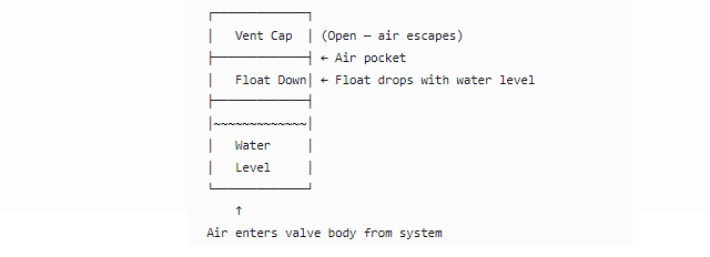
Cycle:
* Air accumulates in the valve body at the system high point
* Water level drops as air displaces water
* Float descends with the water level
* Float opens the vent orifice — air escapes
* Water re-enters the valve body
* Float rises and seals the orifice — cycle repeats
Why Choose WEIZIDOM’s Air Valve for Your HVAC System?
|
Reason |
Benefit |
|
Essential for HVAC System Efficiency |
Removes trapped air that causes noise, reduces heat transfer, creates air locks, and accelerates corrosion — improves system performance and reliability. |
|
Fully Automatic — No Maintenance |
Float mechanism operates automatically without power or intervention — install and forget. |
|
ISO228 Compliant |
Manufactured to international thread standard — ensures compatibility with standard BSP/BSPT threaded fittings worldwide. |
|
Compact Size (DN15–DN25) |
Fits easily at pipeline high points, radiator tops, and air separator outlets — installs in tight spaces. |
|
Brass Construction — Corrosion-Resistant |
Resists rust and scaling in HVAC water systems — longer service life than plastic or iron alternatives. |
|
Cost-Effective Air Management |
Low initial cost plus no operating cost (no electricity) — rapid payback through improved system efficiency and reduced maintenance. |
|
5 Domestic Factories |
Located in Tianjin, Wenzhou, Hebei, Lianyungang, and Shandong, ensuring consistent quality, competitive pricing, and fast delivery. |
|
108+ Export Destinations |
Proven reliability in countries including Mexico, Colombia, Chile, Pakistan, Saudi Arabia, UAE, South Africa, Egypt, and more. |
Technical Specifications
|
Parameter |
Specification |
|
Design Standard |
ISO228 (Pipe Threads for General Purpose) |
|
Diameter Range (DN) |
DN15, DN20, DN25 (NPS ½", ¾", 1") |
|
Pressure Range |
0 – 1.6 MPa (0 – 232 psi) |
|
Medium |
Water, water-glycol mixtures, air (from liquid systems) |
|
Body Material |
Brass (Cu-Zn alloy) — dezincification-resistant |
|
Float Material |
Brass (hollow) or corrosion-resistant polymer |
|
Seat / Orifice Material |
Brass (precision-machined) |
|
Internal Spring (if applicable) |
Stainless Steel |
|
End Connections |
Female threaded — BSP (ISO228) or NPT (ASME B1.20.1) — as specified |
|
Mounting Orientation |
Vertical (preferred) — float mechanism requires upright orientation |
|
Operation |
Fully automatic — no external power required |
|
Vent Orifice Size |
Small (typically 1–3mm) — for continuous air release |
|
Sealing Type |
Float-to-seat — bubble-tight when closed |
|
Testing Standards |
ISO 5208 / EN 12266 |
|
Hydrostatic Test Pressure |
1.5 × rated pressure (2.4 MPa) |
|
Seat Leakage |
Zero (bubble-tight) |
|
Temperature Range |
0°C to +100°C (standard); up to +120°C (high-temp version) |
|
Minimum Operating Pressure |
0.02–0.05 MPa (2–5 psi) — allows venting even at low pressures |
|
Maximum Operating Pressure |
1.6 MPa (16 bar / 232 psi) |
|
Applicable Media |
Chilled water, hot water, water-glycol mixtures (ethylene glycol, propylene glycol up to 50%), mild water treatment chemicals |
|
Body Finish |
Natural brass (uncoated) or nickel-plated — as specified |
Customized options (NPT threads, nickel-plated finish, high-temperature version, integrated manual vent, larger orifice for faster venting) available upon request.

Installation Notes for HVAC Systems
To ensure proper operation of the Air Valve:
|
Installation Guideline |
Reason |
|
Install at the highest points of the piping system |
Air naturally rises to high points — installing elsewhere may not capture all trapped air. |
|
Install vertically with the vent cap pointing UP |
Float mechanism requires vertical orientation to operate correctly. |
|
Install an isolation valve (ball valve or gate valve) below the air valve (recommended) |
Allows removal or replacement of the air valve without draining the entire system. |
|
Do not install in locations subject to freezing |
Ice can damage the float and body — install in conditioned spaces or use heat tracing. |
|
For systems with dirty water or debris, install a strainer upstream |
Debris can block the small vent orifice — strainer extends service life. |
|
For systems with high air content (during initial fill), consider larger or multiple air valves |
Standard air valves are designed for continuous release of small air pockets — large volumes may require additional venting. |
|
Allow adequate clearance for air discharge |
Vent must be open to atmosphere — do not install in enclosed spaces where escaping air or water spray could cause damage. |
|
For glycol mixtures, verify compatibility with brass |
Standard brass is compatible with most ethylene and propylene glycol mixtures up to 50%. |
Air Valve Placement in HVAC Systems — Typical Locations
|
Location |
Reason |
Recommended Size |
|
High points on supply and return mains |
Air accumulates at high points in main distribution piping |
DN20–DN25 (¾"–1") |
|
Top of radiators |
Individual radiator air venting |
DN15 (½") |
|
Top of air separators |
Captures air separated by centrifugal action |
DN20–DN25 (¾"–1") |
|
Pump suction line high points |
Prevents air from entering pump |
DN15–DN20 (½"–¾") |
|
Expansion tank connections |
Vents air from expansion tank |
DN15–DN20 (½"–¾") |
|
Vertical riser tops |
Air accumulates at top of riser before horizontal turn |
DN20–DN25 (¾"–1") |
|
Coil connections (AHU/FCU) |
Local air venting at terminal units |
DN15 (½") |
Symptoms of Trapped Air in HVAC Systems
|
Symptom |
Cause |
Solution |
|
Gurgling or bubbling noises in pipes |
Air moving through water |
Install air valves at high points |
|
Reduced heat output from radiators |
Air pocket blocks water flow |
Vent air from radiators |
|
Uneven cooling from fan coil units |
Air in chilled water lines |
Install air valves at system high points |
|
Pump cavitation noise |
Air entering pump suction |
Vent air from pump suction line high points |
|
Water hammer (banging pipes) |
Trapped air compressing and releasing |
Remove air from system |
|
Difficulty filling system |
Air lock preventing water flow |
Vent air during filling process |
|
Corrosion / black water |
Oxygen in water causing rust |
Remove air to reduce oxygen content |
