
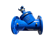
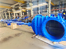
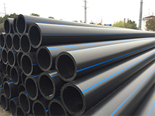
- Gate valve
-
- DN1000 Extension stem double flange soft seal gate valveDIN F4 resilient seated gate valveDN450-1200 Resilient Seated Gate ValveDIN F5 resilient seated gate valveSocket connection soft seal gate valveUnderground cap soft seal gate valveBS5163 rising stem soft seal gate valveHard seal gate valveAPI slab Gate ValveStainless steel flange gate valveWafer knife gate valvePneumatic gate valveSoft seal gate valveExtension stem gate valveUL/FM fire protection groove ends gate valveRising stem forged steel gate valvecarbon steel gate valveStainless steel threaded gate valveDIN soft seal gate valveANSI soft sealing gate valve 200PSICast iron gate valveBS resilient seated gate valve
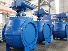
- Butterfly valve
-
- DN900 pneumatic triple eccentric hard seal butterfly valveD643H Triple Eccentric Butterfly ValveD343H Hard seal butterfly valveMulti standard EPDM seated butterfly valveSingle flange butterfly valveDN2000 Double eccentric butterfly valveFlange butterfly valveLug butterfly valveWafer butterfly valve with handleWorm gear operated butterfly valveWafer lined fluorine butterfly valveStainless steel wafer butterfly valveStainless steel flanged butterfly valveThree eccentric flange butterfly valvePneumatic flanged butterfly valvePneumatic wafer butterfly valveTriple eccentric butterfly valve wafer typeWafer butterfly valve ULC approvedInflatable seat butterfly valveHigh performance butterfly valveGrooved end butterfly valveElectric soft seal butterfly valveFlange fluorine lined butterfly valveHandle aluminum butterfly valveWorm Gear Aluminum Butterfly ValveFull PTFE lined butterfly valve wafer typeOne stem no-pin wafer butterfly valveMulti standard aluminum stem butterfly valveStainless Steel wafer Butterfly ValveAluminium handle operated lug butterfly valveLever Operated Flange Butterfly ValveButterfly valve stemButterfly valve discButterfly valve seat
- Ball valve
-
- DN1400 top-mounted eccentric semi-ball valveFlanged three-way ball valveFully welded ball valveNatural gas ball valveHigh platform flange ball valve1 PC ball valveFixed ball valvePTFE seat flanged ball valveMetal seat ball valveAPI 6D ball valve3 Piece ball valveFull Bore 3 way ball valve L-Port3 Way T-Port ball valve2PC Ball valve female thread stainless steel
- Globe Valve
-
- API Carbon Steel Globe ValveBellows Globe ValveStainless steel flange globe valveStainless steel thread S type globe valveStainless steel thread B type globe valveCast Steel Globe ValvePiston Globe ValveWCB Carbon Steel Globe Check Valveelectric motorized control stainless steel SS316 globe valveBrass Globe ValveCryogenic Globe valveHT200 Globe ValveThreaded Stainless Steel Globe ValveGG25 Globe ValveANSI API Cast Steel And Stainless Steel Globe valve
- Check valve
-
- Rubber seal check valveDN800 Slow closing check valveDN800 Rubber Disc Check ValveButterfly Buffering Check Valvecheck valve with counter weightSilent Check ValveWCB Swing check valveSwing Check ValveSingle Chip Check Valve H74WStainless Steel Wafer Check ValveSwing Start Check ValveFoot check valveAPI Swing Check ValveDIN Flange check valveSingle plate check valveLifting Check ValveBottom ValveHammer Diminish Noises Check ValveWafer Check ValveWafer dual plate check valve
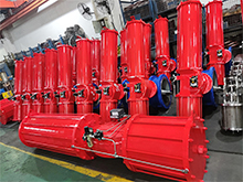
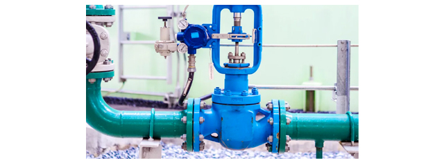
- Control valve
-
- Static Balancing ValveCage Guided Sleeve Globe Control ValveDN1000 Piston Flow Regulating ValveDN1600 Electric Actuator Flow Regulating ValvePneumatic Flanged Butterfly ValvePneumatic Wafer Butterfly ValveAngle Seat ValvePneumatic gate valveElectric three-way control valveElectric sleeve control valve
- Water Meter
-
- Vertical Type Water MetersStainless steel threaded water meterPiston water meterPlastic water meterMore flow rotor dry water meterspiral vane flange water meterCI wotlman water meter with pulse outputLXCLG(R) Vertical removable element woltman cold (hot) water meterSingle flow rotor dry water meterPrepaid Token Water MeterElectromagnetic flowmeterRotary Piston Liquid Sealed Water MeterRotary Piston Liquid Sealed Water Meter
- Air valve
-
- Double ball exhaust valveDoubleair Air Valve SaudiDoubleair Air Valve Southeast AsiaDoubleair Air Valve South AmericaDouble Air ValveThreaded Air ValveSingle Air ValveTriple Functions Air ValveAutomatic Air Release ValveAutomatic release valveAutomatic exhaust valveComposite Exhaust Air ValveBrass exhaust valveDouble Ball Air Valve
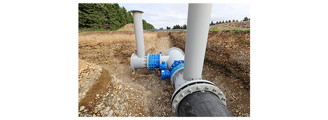
- Pipe Repair & Coupling
-
- Flexible Multi-Function Pipe Coupling ZFJ-SSS Semi-Circle Pipe Repair Clamp SJW-HDuctile Iron Band Repair ClampStainless Steel Band Repair ClampDouble-Section Pipe Repair CouplingFolding Type Pipe RepairSingle-Section Multi-Function Pipe Coupling MF-SGear-Ring Type Multi-Function Pipe Coupling GR-SZBW Damping Corrugated Hose
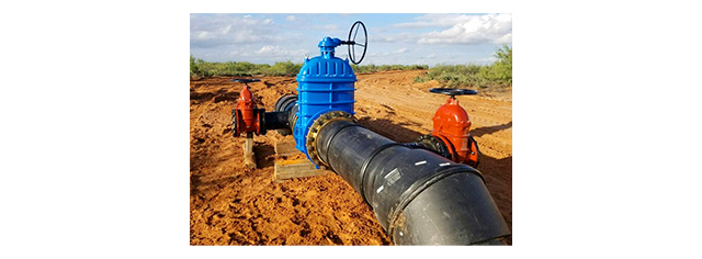
- Dismantling Joint
-
- VSSJAFC(CC2F) Detachable Flange Transmission JointVSSJA-2(B2F) Double Flange Limited Expansion JointVSSJA-1(BF) Single Flange Limited Expansion JointVSSJA(AF) Flange Loose Expansion JointJGD-B Threaded Rubber JointZBW Damping Corrugated HoseKXT-S Flexible Dual-Spherical Rubber JointKXT Rubber Soft JointFlange Adaptor
What is the most common gate valve for water supply system?
Common valves and uses for water treatment
During use, you should avoid opening the gate a small amount, because the erosion of the high-speed flowing medium will accelerate the damage of the sealing surface. The gate moves up and down in a plane perpendicular to the center line of the gate seat channel, cutting off the medium in the pipeline like a gate, so it is called a gate valve.
Gate valve features:
① Small flow resistance. The internal medium channel of the valve body is straight, the medium flows in a straight line, and the flow resistance is small.
② It requires less effort when opening and closing. It is compared with the stop valve, because whether it is open or closed, the movement direction of the gate is perpendicular to the direction of medium flow.
③ Large height, long opening and closing time. The opening and closing stroke of the gate is relatively large, and the lowering is carried out through the screw.
④ Water hammer is not easy to occur. The reason is the long shutdown time.
⑤ The medium can flow in any direction on both sides and is easy to install. The gate valve passage is symmetrical on both sides.
⑥ The structural length (the distance between the two connecting end faces of the shell) is small.
⑦ The sealing surface is easy to wear and affects the service life. When opening and closing, the two sealing surfaces of the gate plate and the valve seat rub and slide against each other. Under the action of the medium pressure, scratches and wear are easy to occur, which affects the sealing performance and shortens the service life.
The globe valve is a closed-circuit valve that uses the disc (the closing part of the stop valve is called the disc) to move along the center line of the disc seat (valve seat) channel to control the opening and closing of the pipeline.
Globe valves are generally suitable for transporting liquid and gaseous media under various pressure and temperature conditions within the specified standard range, but are not suitable for transporting liquids containing solid precipitation or precipitated crystals. In low-pressure pipelines, stop valves can also be used to regulate the flow of media in the pipeline.
Due to structural limitations, the nominal diameter of the stop valve is below 250mm. If it is on a pipeline with high medium pressure and high flow rate, its sealing surface will wear out quickly. Therefore, when the flow needs to be adjusted, a throttle valve must be used.
① The wear and scratches on the sealing surface are not serious, so the operation is more reliable and the service life is long.
② The sealing surface area is smaller and the structure is simpler. The man-hours required to manufacture the sealing surface and the precious materials required for the sealing ring are less than those of the gate valve.
③ When opening and closing, the valve disc stroke is small, so the cut-off valve height is small. Easy to operate.
④ By using the thread to move the valve disc, there will be no sudden opening and closing, and the "water hammer" phenomenon will not easily occur.
⑤ The opening and closing torque is large and it is more laborious to open and close. When closing, the movement direction of the valve disc is opposite to the direction of the pressure of the medium movement, and the force of the medium must be overcome, so the opening and closing torque is large. Therefore, it affects the application of large diameter stop valves.
⑥ The flow resistance is large. The stop valve has the greatest flow resistance among all types of stop valves.
⑦ The medium flow direction is unidirectional. It should be ensured that the medium flows from bottom to top, so the medium must flow in one direction.
Butterfly valve is a rotary valve that uses a disk-type (also called butterfly plate) opening and closing part to rotate 90° or about 90° to open and close the channel. The movement of the butterfly valve disc is wiping, so most butterfly valves can be used in media with suspended solid particles.
Commonly used butterfly valves include wafer butterfly valves and flange butterfly valves. Wafer-type butterfly valves use studs to connect the valve between two pipe flanges. Flange-type butterfly valves have flanges on the valve, and bolts are used to connect the flanges at both ends of the valve to the pipe flanges.
① The appearance is small, the length is short, the structure is simple and the weight is light.
② Easy to operate, quick to open and close, just rotate the valve disc 90° to open and close
③ The sealing and adjustment performance are good. Since the rubber is used as the sealing ring, the compression and resilience are good (that is, it will not harden), so the sealing is good. The valve disc can perform sensitive flow control when it is opened between 15° and 70°.
④ Small operating torque and fluid resistance. According to measurements, the fluid resistance of butterfly valves is smaller than other types of valves except ball valves.
⑤ Due to the limitation of sealing material, the operating pressure and operating temperature range of butterfly valves are small.
The check valve is a valve used to prevent the medium in the pipeline from flowing back. It opens when the medium flows forward and automatically closes when the medium flows backward. It is generally used in pipelines that do not allow the medium to flow in the opposite direction to prevent the reverse flow of medium from damaging equipment and components.
Do not cause the rotary pump to reverse when the pump is stopped. In pipelines, check valves and closing valves are often used in series. This is due to the poor sealing of the check valve. When the medium pressure is small, a small part of the medium will leak, and a closing valve is required to ensure the closure of the pipeline.
The bottom valve is also a kind of check valve. It must be submerged in the water and is specially installed at the front end of the suction pipe of a water pump that cannot self-prime or does not have vacuum pumping and water diversion.
After the valve has been running in the pipeline network for a period of time, various failures will occur. One is related to the number of parts that make up the valve. The more parts, the more common faults. The second is related to the quality of valve design, manufacturing, installation, operating conditions, and maintenance.
1. Transmission failure
Transmission failure often manifests as valve stem jamming, inflexible operation, or valve inoperability.
① The valve rusts after being closed for a long time;
② Improper installation operation damages the valve stem thread or valve stem nut;
③ The gate is stuck in the valve body by foreign matter;
④ The gate is often in a half-open and half-closed state, and the valve stem screw and valve stem nut wire are misaligned, loosened, and seized due to hydraulic or other impact forces;
⑤ The packing is pressed too tightly and locks the valve stem;
⑥ If the valve stem is pushed or stuck by the closing member, the transmission part should be lubricated during maintenance;
⑦ Use a wrench and tap gently to eliminate sticking and pushing;
① Causes of valve body damage and rupture:
② The corrosion resistance of the valve material decreases;
③ Pipeline foundation settlement;
④ The pipe network pressure or temperature difference changes greatly;
⑤ Water hammer;
⑥ Improper operation of closing valve, etc.
External causes should be eliminated promptly and valves or valves of the same model should be replaced.
The symptoms of valve leakage are:
① The valve stem core is leaking;
② The gland is leaking;
③ The flange rubber gasket is leaking.
Common reasons include:
① The valve stem (valve shaft) is worn, corroded and peeled off, and the sealing surface is pitted and peeled off;
② Seal aging and leakage;
③ The gland bolts and flange connecting bolts are loose.
④ Add and replace sealing media during maintenance;
⑤ Replace the new nut and readjust the position of the fastening bolt.
No matter what kind of fault, if repairs and maintenance are not timely, it may cause a waste of water resources, and even worse, cause the entire system to be paralyzed. Therefore, valve maintenance personnel must be well aware of the causes of valve failures, be able to skillfully and accurately adjust and operate valves, handle various emergency failures promptly and decisively, and ensure the normal operation of the water treatment pipe network.
The symptoms of poor valve opening and closing include the valve not opening or closing, and the valve not operating normally.
The reasons are:
① The valve stem is corroded;
② The gate is stuck or the gate is rusted when it is closed for a long time;
③ The gate falls off;
④ Foreign matter is stuck in the sealing surface or sealing groove;
⑤ The transmission parts are worn or jammed.
In the above situation:
① Repair and lubricate transmission parts;
② Repeatedly opening and closing valves and impacting foreign objects with water;
③ Replace the valve.
1. Cleaning of valves
The surface of the valve, the trapezoidal thread on the valve stem and valve stem nut, the sliding part of the valve stem nut and bracket, as well as gears, worm gears and other components are easily contaminated with dust, oil, media residue and other dirt, which will cause wear and corrosion to the valve. . Therefore, it is necessary to keep the outside and moving parts of the valve clean; protect the integrity of the valve paint.
The trapezoidal thread of the valve, the sliding parts of the valve stem nut and bracket, the bearing parts, the meshing parts of gears and worm gears, worms, and other cooperating parts all require good lubrication conditions to reduce mutual friction and avoid mutual wear. Lubricated parts should be refueled regularly according to specific conditions.
① For valves in operation, all valve parts should be complete and intact.
② The bolts on the flange and bracket are indispensable. The threads should be intact and no loosening is allowed.
③ If the fastening nut on the handwheel is found to be loose, tighten it in time to avoid wearing the connection or losing the handwheel and nameplate.
⑤ If the handwheel is lost, it is not allowed to use an adjustable wrench to replace it, and it should be replaced in time.
⑥ The packing gland is not allowed to be skewed or have no preload gap.
⑦ The scale on the valve should be kept complete, accurate and clear.
⑧ The valve seals, caps, pneumatic accessories, etc. should be complete and intact.
⑨ If it has an electric or pneumatic drive device, it should be maintained and maintained in strict accordance with the corresponding operation manual.